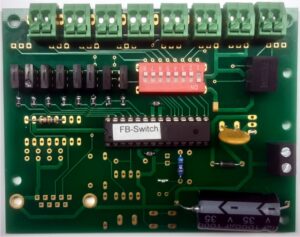
With these modules, the cars can be controlled without a digital command station. In short, the operation is as follows: A chip on the print continuously sends a command to the connected infrared LED which is place along the road. This IR LED, in turn, transfers commands to a car that comes within range of the infrared LED (15 – 20 cm). The transferred command is received and processed by every DC-Car and therefore works independently of the decoder address. By connecting the infrared LED’s via switches or relays contacts to, we can let the cars perform certain functions at certain spots, such as e.g. light ON/OFF, accelerate/decelerate, stop, etc. The module has eight outputs which each transmitting it own fixed command. These eight commands together are called a command group. In the past, there were 8 different modules (A to H) with each it’s own command group. Since we now have the new function module SW it has become possible to generate one of the 8 previous modules by means of dip switches. This new module replaces the old modules A to H and made it possible to have more then 8 command groups. The amount of groups is still growing nowadays.
As mentioned above, each module has eight outputs for connecting infrared LED’s, which control the various functions in the cars. The LED’s are placed along the road, where a certain function has to be switched ON or OFF. With the function module you can obtain a varied driving behavior without the use of a digital command station or a PC. The use of the infrared stop function of a module ensure that the cars are stopped. The cars have a built-in acceleration delay and will therefore slowly accelerate again when the stop command is OFF. The functions are so divided between the different command groups so that meaningful combinations are always available.

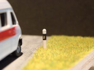
The IR LED’s are placed along the road. We have IR LED’s build into a delineator post . The IR LED’s can be small and almost invisible. You are of course free to hide the IR LED’s in other scenery items like trash cans, under parked cars, into bushes, etc. etc.
The function module comes with eight 3 mm IR LED’s and eight current limiting resistors (270 Ohm) so you can start learning and evaluating the system right away. IR LED’s may be connected to a total of 1 Amp current. In practice this means you can have over 50 IR LED’s to be connected. This is enough for an average model layout.
It is also possible to add more then one output command to a single IR LED in that case you have to use diodes to separate the various commands.
You can only combine commands from one and the same Function module.
Mixing from different module is not allowed.
Some examples of a command group are listed her under, for a complete list please check the DC-Car wiki.
Command group A has general functions (Dip switch 1=ON):
Connection 1: Speed step 0 (works like the Faller stop coil)
Connection 2: Lighting ON
Connection 3: Lighting OFF
Connection 4: Left indicator ON
Connection 5: Right indicator ON
Connection 6: Indicators OFF
Connection 7: Speed step 14
Connection 8: Speed step 28
Command group B features the functions of a emergency vehicle (Dipswitch 2=ON):
Connection 1: Speed step 0 (works as the Faller stoppool)
Connection 2: Hazard lights ON
Connection 3: Hazard lights OFF
Connection 4: Blue lights ON
Connection 5: Blue lights OFF
Connection 6: Front flashers ON
Connection 7: Front flashers OFF
Connection 8: Speed step 28
Command group C has the extensive lighting functions and more speed steps (Dipswitch 3=ON). Interesting are the speed step function +2 and –2. This allows, for example, uphill, more gas or downhill to reduce the speed.
Connection 1: Lighting output 2 TO
Connection 2: Lighting output 2 OFF
Connection 3: Lighting output 3 ON
Connection 4: Lighting output 3 OFF
Connection 5: Increase speed by 2 steps
Connection 6: Reduce speed by 2 steps
Connection 7: Speed step 10
Connection 8: Speed step 21
Command group D Used for automatic parking functions (Dipswitch 4=ON).
Connection 1: Stop and switches OFF the indicator lights (Stop time adjustable with CV 108)
Connection 2: Stop with left direction indicators ON (Stop time adjustable with CV 108)
Connection 3: Stop right direction indicators on (Stop time adjustable by CV 108)
Connection 4: Stop with alarm lights on (Stop time adjustable CV 108)
Connection 5: Driving/pulling up with lane as specified in CV 110 and direction indicators FROM Junction 6: Driving/pulling up with lane as specified in CV 110 and direction indicator to the left (blinking time adjustable by means of the CV 109)
Connection 6: Driving/moving with lane as specified in CV 110 and direction indicators on the right (blink time adjustable by means of CV 109)
Connection 7: Driving/moving up with lane as specified in CV 110 and alarm lights ON (blink time adjustable by means of CV 109)
This is just a part of the total available command lists, please check the DC-Car wiki for the latest status and complete list of command groups.


